REALISTIC NEUTRON SPECTRA FOR RADIATION PROTECTION
AND OTHER APPLICATIONS AT AERI, BUDAPEST
J. Pálfalvi 1), L. Sajó-Bohus 2) and M. Balaskó 1)
1) Atomic Energy Research Inst. P.O.B. 49, H-1525 Budapest, Hungary
2) Simon Bolivár University, Ap. 89000, Caracas, Venezuela
Keywords: neutron spectra, neutron radiography, neutron beam formation, neutron dosimetry
INTRODUCTION
The BRR is a tank type reactor, moderated and cooled by light water.
The cylindrical tank made of Al alloy has a diameter of 2300 mm and
the height is 5685 mm. The heavy concrete reactor block is situated
in a rectangular, semi-hermetically sealed hall, its area is 600 m2.
The core is arranged in a hexagonal lattice with a pitch of 35 mm
and contains 229 fuel rods, the 235U enrichment is 36%. The core
is surrounded by removable and fixed Be reflectors. The nominal
thermal power is 10 MW which results in a thermal flux of about 2*1014
n/cm2s, meanwhile the total flux is 3*1014 n/cm2s. Three out of the 10
horizontal channels were constructed in a way to facilitate the versatile
use of them, providing different irradiation geometries.
The following variable parameters characterize these beams:
The importance of constructing reference neutron radiation fields with energy spectra that more closely simulate spectra found in workplaces became clear in recent years and inspired us to build up our facilities.
BIOLOGICAL IRRADIATION FACILITY (BIF)
The 5th horizontal channel was selected for constructing the BIF. It started with the calculation
of the leakage spectra from the core at the channel taking into consideration Be and Al materials
as reflectors, or beam couplers, with different thickness. It was found that the Be more drastically
modifies the spectrum than the Al, decreases the fast fraction and increases the thermal and epithermal
flux (see Figs. 1&2). In order to be flexible the following solution was accepted. The Be reflector
rods originally positioned in front of the channel were modified: cutting out a window which was
replaced by Al. Also the steady Be reflector was drilled through and an Al plug was inserted. Thus,
the thickness of the Al beam coupler is 140 mm. This resulted in a quite hard spectrum, but
providing the possibility to soften it – if necessary – by different filters placed inside the beam tube.
The modified Be-Al rods can be removed and pure Be rods inserted again if a softer starting
spectrum is needed.
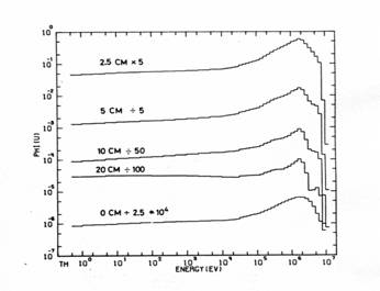
Fig. 1 The effect of the Be reflector on the shape of the leakage spectrum on the dependence of the thickness. The calculated core spectrum without any reflector is marked as 0 cm.
The 3330 mm long beam tube was divided into 3 segments. The 1st one, in a distance of 1900 mm from the core is the beam shutter of 715 mm made of iron and heavy concrete. The next one is a rotatable heavy concrete disk having six cylindrical holes for filters: open window, 50, 100, 150 and 200 mm of Bi and 200 mm of Pb. The last unit is a tank of 480 mm long for any liquid which can be pumped in and out. The tank is separated from the filter by a 20 mm thick Pb disk, not removable, the wall of the tank is made of Al exhibiting another not removable filter of 15 mm. There is an additional Fe disk of 20 mm, effective only when the Pb filter is selected. The outer orifice of the beam tube joins to a collimator having a length of 1400 mm. Manually changeable filters can be place inside or in some cases samples can be irradiated here. In front of this collimator there is a variable space for irradiation, surrounded by several layer of shielding materials (borated water, paraffin, heavy concrete and lead).

Fig. 2 Spectrum modifying effect of the Be beam coupler vs. the thickness. O stands for the mean energy of the spectrum; • is related to the transmitted fraction and ∇ marks the fast neutron (> 1 MeV) fraction of the spectrum. Thermal neutrons were neglected.
Many filter combinations can be used to simulate operational spectra at power reactors. In Fig. 3 two such spectra are presented (Sp1, Sp2) together with the leakage spectrum from the Al beam coupler (Sp4). For comparison the lead shielded SILENE spectrum [1] is given (Sp3). Beside the fix filters and the beam coupler the following filters are used. For Sp1: 4 mm Al, 45 mm Pb, 30 mm Fe and 200 mm Bi; for Sp2: 27 mm Al, 45 mm Pb, 20 mm Fe, 200 mm ordinary concrete and 10 mm B4C. The spectra can be evaluated if some characteristic quantities are compared as shown in Table 1. With increasing mean energy both the ambient dose equivalent conversion factor and the response of the LB6411 survey meter is increasing, meanwhile the Bonner sphere ratio is decreasing [2]. It is should be mentioned that the H*/LB6411 ratio is constant within 2% (343.5 ± 6.1) in this energy range. (Thermal neutrons were neglected)
Table 1 Calculated dosimetric quantities for spectra presented in Fig. 3, The 3“/9.5” Bonner sphere signal ratios were calculated for 3He detectors. The LB6411 response is normalized to 1 for bare Pu-Be spectrum.
| Quantities | Sp1 | Sp2 | Sp3 | Sp4 |
| 3"/9.5" ratio | 1.14 | 1.17 | 0.94 | 1.38 |
| Mean E (keV) | 534 | 510 | 813 | 474 |
| H* (pSvcm2) | 174 | 171 | 201 | 151 |
| LB6411 Resp. | 0.50 | 0.49 | 0.59 | 0.45 |

Fig. 3 Leakage and filtered spectra at the BIF: Sp4, Sp1 and Sp2, respectively; the lead filtered SILENE spectrum is marked as Sp3 [1].
In the following Table 2 typical fast neutron dose rate and flux values are presented mostly used for biological experiments. Only the changeable filters are mentioned.
Table 2 Fast neutron (E>100 keV) absorbed dose rate in water and flux values for typical filter assemblies at BIF
| Filter thickness in mm |
Dose rate mGy/s |
Flux 106 n/cm2s |
| 200Pb+20Fe+45Pb+10B4C | 0.0233 | 2.17 |
| 150Bi+454Pb+10B4C | 0.172 | 16.2 |
| 50Bi+454Pb+10B4C | 1.32 | 120 |
| 50Bi+10B4C | 2.81 | 260 |
| 100 PMMA | 2.99 | 277 |
| 45Pb+10B4C | 4.36 | 405 |
| Direct beam | 7.58 | 700 |
DINAMIC NEUTRON RADIOGRAPHY UNIT (DNRU)
This very versatile unit was built at channel 2, having a fix beam coupler made of 90 mm Be +10 mm Al.
This arrangement provides softer spectrum than it is at the BIF, with a large amount of thermal neutrons.
The beam shutter of 965 mm was made of iron and heavy concrete. In the beam tube there is a pin-hole
collimator with a diameter of 25 mm, the collimation ratio is 170. The beam tube joins to a beam
formation and filtering unit shown in Fig 4. It is equipped with movable Cd and In filters, both of them
are 2 mm thick and can be used separately or simultaneously in order to vary the thermal to intermediate
flux ratio meanwhile the fast flux remains unchanged. In Table 3 the flux values are presented for several
beam formation arrangements. The maximum beam diameter is limited to 20 cm but the irradiation area is
equipped with a special, remote controlled sample holder system which allows to move the samples horizontally
and also vertically, covering an area of 60 by 80 cm2. In this way, large objects as phantoms, can be irradiated [3].
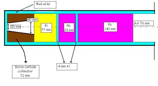
Fig. 4. The beam formation and filtering unit at channel 2 of BRR. The diaphragms and the Cd and In
filters are remotly controlled.
Table 3 Typical flux values at the DNRU of BRR in 106 n/cm2s. The fast region starts at 100 keV
LOW REFLECTION IRRADIATOR (LRI)
For such experiments where the back scattered neutrons from the shieldings can be disturbing a special irradiation
area was constructed at the channel 3. The beam coupler and the shutter are the same as at the DNRU but the
collimator is different as shown in Fig. 5.
Fig. 5 The collimator system at the LRI of BRR
The collimator-filter assembly can be changed if necessary. The irradiation area is not furnished with fixed elements
or devices, therefore for each experiment the appropriate design can be applied. The beam stop was shaped to form
a chamber with walls made of B4C and borated water or polyethylene (PE) to decrease the backscattering. The
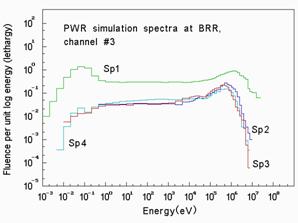
calculated leakage spectrum behind the Be reflector and the measured one at the target area are shown in Fig. 6.
Here we present also two simulation spectra for comparison (GRENF and PWR [4,5]. Some related dosimetric quantities
are presented in Table 4.
Fig. 6 Spectra at LRI. Sp1 is the leakage spectrum behind the Be reflector, Sp2 is the filtered one at the target area.
Sp3 and Sp4 are simulation spectra GRENF and PWR [4,5].
Table 4 Calculated dosimetric quantities for spectra presented in Fig. 6. For more explanation see Table 1.
NEUTRON CALIBRATION LAB (NCL)
In addition to the reactor fields, isotopic neutron sources are in use in the NCL. Here the field is monitored
by a Long Counter and by a LB6411 type of survey meter. Shadow cones and movable walls made of polyethylene and
carbon facilitate the study of different neutron fields.
There are phantoms for dosimetry research: BOMAB, elliptical chest filled with tissue equivalent liquid or water,
ICRU sphere, slab filled with water, specially constructed sliced slab where detectors can be inserted and made
of PMMA. A set of Bonner spheres and semiconductor detectors with n,α and n,p converters are available for
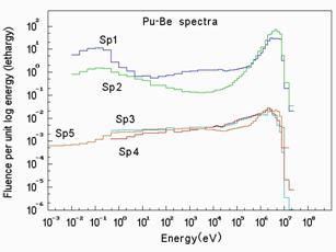
spectrometry. Few measured spectra are presented in Fig. 7 and some characteristic dosimetry quantities are
summarized in Table 5. The Sp1 and Sp2 were measured in 1 m distance from the source using a cylindrical
collimator/moderator made of PE and a collimator made of borated PE, respectively. In the case of Sp3 and
Sp4 a spherical PE moderator was used and the spectra were measured in 4 and 3 m distances. The Sp 5 is a
stray spectrum measured in a Pu reprocessing plant [6].
Fig. 7 Stray Pu-Be spectra (Sp 1-4) at the NCL of AERI and in a Pu reprocessing plant (Sp5) [6].
Table 5 Calculated dosimetric quantities for spectra presented in Fig. 7. For more explanation see Table 1.
SUMMARY
Recently there are 26 different spectra – from the nearly pure thermal at BIF to the hard bare Pu-Be at
NCL – available at the AERI. The staff is co-operating with numerous institutions and performs irradiation
for request, scientific and industrial studies are in progress, also national and international dosimetric
intercomparisons and trainings are taken place from time-to-time. Because of the versatility of the 4 systems,
new neutron fields can be design and constructed for demand.
REFERENCES
[1] B. Tournier, F. Barbry and B. Verrey, Rad. Prot. Dos. 70 (1997) 345.
1 Dr. J. K. Pálfalvi, E-mail: palfalvi@sunserv.kfki.hu , fax: 361 395 9162

Beam formation
Thermal
Intermediate
Fast
Narrow beam (NB)
89
6.8
79
Broad beam
76
7.3
78
NB with 2mm In
21
5.8
76
NB with 2mm Cd
<0.02
6.4
76
Quantities
Sp1
Sp2
Sp3
Sp4
3"/9.5" ratio
1.38
1.15
1.81
1.49
Mean E (keV)
532
406
222
232
H* (pSvcm2)
154
173
116
133
LB6411 Resp.
0.45
0.47
0.32
0.35
Quantities
Sp1
Sp2
Sp3
Sp4
Sp5
3"/9.5" ratio
0.32
0.12
0.97
0.69
0.71
Mean E (keV)
2.16
3.52
1.5
1.29
1.49
H* (pSvcm2)
318
386
188
223
233
LB6411 Resp.
1.5
1.29
0.57
0.68
0.74
[2] A. Aroua, M. Grecescu, S. Pretre and J.F. Valley, Rad. Prot. Dos. 54 (1994) 99.
[3] M. Balaskó, J. Pálfalvi and E. Sváb, Proc. 6th Word Conf. on Neutron Radiography, 17-22 May, Osaka Japan, 1999.
[4] J.L. Chartier, B. Jansky, H. Kluge, H. Schraube and B. Wiegel, Rad. Prot. Dos. 70 (1997) 305.
[5] O.F. Naismith and B.R.L. Siebert, Rad. Prot. Dos. 70 (1997) 241.
[6] D.T. Bartlett, A.R. Britcher, A.G. Bardell, D.J. Thomas and I.F. Hudson, Rad. Prot. Dos. 44 (1992) 233.